FLIP TOP CAP MOULD
Flip Top Cap Moulds for In-Mould and External Closing
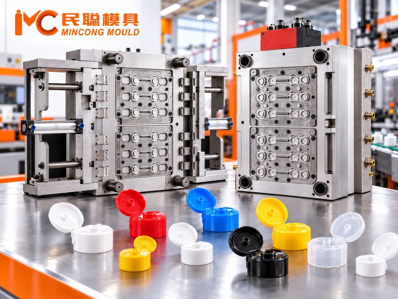
Custom flip top cap moulds for cosmetic, food and household closures. We review the living hinge, cavity balance, cooling, ejection and injection-machine limits, then choose an in-mould or external closing route to suit the cap and production line.
ENGINEERING FOCUS
What Makes a Flip Top Cap Mould Different?
A flip top closure combines the cap body, lid and living hinge. The mould must fill the hinge without weakening it, release the open cap without distortion and deliver consistent closing behaviour across cavities. We select the closing route alongside the machine stroke and part-handling plan.
Living Hinge Formation
Gate position, melt flow and cooling influence how the hinge fills and flexes. The hinge should be considered together with the selected material and cap geometry. Review the PP living-hinge design checks before tooling.
Closing Consistency
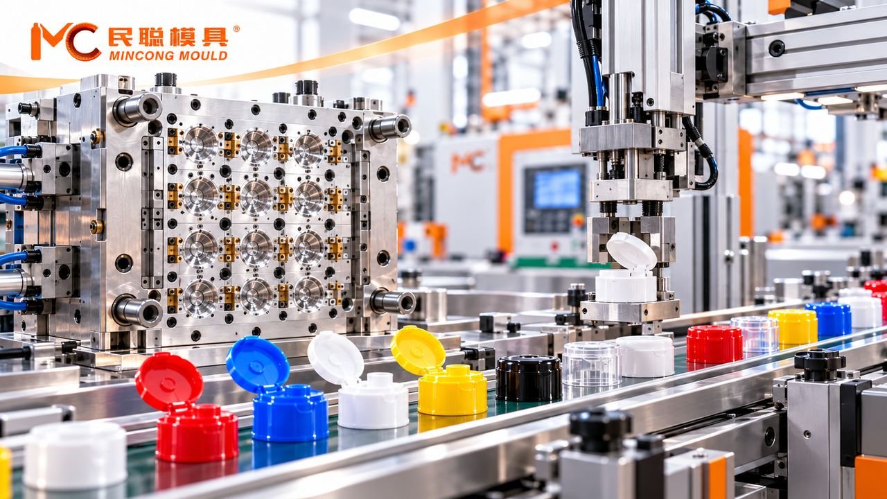
For automatic closing or in-mould closing, the cap must leave the mould in a repeatable position and complete the closing action reliably.
Cavity Balance
As cavity count increases, melt distribution and cooling consistency become more important. Higher cavity count only creates value when part quality remains consistent.
Ejection & Movement
The mould opening sequence, ejection and closing mechanism must work together without damaging the hinge, sealing area or cosmetic surfaces.
Flip Top Cap Mould Configuration
Final specifications are selected according to the cap design, injection machine and target production output.
| Mould Type | Custom flip top cap injection mould |
| Typical Product Material | PP or project-specific material |
| Cavity Number | Project-specific; evaluated against cap size, target output and machine capacity |
| Runner System | Hot runner or cold runner |
| Hot Runner | YUDO in the featured configuration; runner selection is reviewed for each project |
| Cavity / Insert Steel | FS136 in the featured automatic-closing configuration |
| Closing-Mechanism Components | FS136 in the featured configuration |
| Main Mould Plates | 4Cr13 in the featured automatic-closing configuration |
| Closing | Automatic closing, in-mould closing or external automation depending on the cap |
| Ejection | Push plate or project-specific ejection structure |
| Critical Dimensions | Defined and verified against the approved cap drawing and inspection plan |
| Service Life | Specified according to steel selection, mould structure, maintenance plan and operating conditions |
| Automation | Automatic closing, robot handling and production integration options |
RUNNER SELECTION
Hot Runner or Cold Runner?
Hot runner is not automatically the better solution, and cold runner is not simply a lower-cost choice. The decision should be made around the actual production conditions.
- Cap size and part weight
- Required cavity number
- Injection-machine tonnage and shot capacity
- Tie-bar spacing and mould-size limits
- Material waste target
- Automation method
- Maintenance preference
- Expected production volume
The mould and the machine must be evaluated together.
For high-volume multi-cavity production, a balanced hot runner can improve material efficiency and filling consistency. For projects with machine-size restrictions or specific investment requirements, a carefully designed cold-runner solution may be more practical. Review the hot-runner and cold-runner trade-offs; for a proposed hot runner, compare hot-tip and valve-gate options against the resin, gate requirements, controls and maintenance plan.
Automatic Closing Flip Top Cap Mould
Representative 12-Cavity Automatic-Closing Configuration
- Mould configuration: 12 cavities with automatic closing and a YUDO hot runner.
- Main mould plates: 4Cr13.
- Cavities, inserts and closing-mechanism components: FS136.
- Injection machine: a 250T machine for this representative configuration.
- Indicative cycle: approximately 20 seconds on a conventional injection machine.
Machine selection must be checked against the actual cavity count, cap geometry, shot capacity, tie-bar spacing, mould dimensions and opening stroke. Cycle time varies with the resin, cooling, cap design and machine settings; these figures are reference values for this configuration rather than a guarantee for every project.
Planning a similar project? Check the injection-machine compatibility requirements before selecting a cavity layout. Agree on hinge condition, lid alignment, snap engagement and any required sealing checks across cavities and repeated cycles using our automatic-closing mould trial checklist.
Closing-Mechanism Maintenance
Keep the closing mechanism properly lubricated. For this configuration, plan a stop after approximately 10 hours of operation to inspect the mould, allow cooling and lubricate the closing mechanism before resuming production. Confirm the inspection and lubrication schedule for the specific mould and operating conditions.
For suitable flip top designs, Mincong can integrate automatic closing or in-mould closing so the cap leaves the mould in the required condition without relying on manual closing. This function should be considered from the beginning of mould design because it interacts with the living hinge, opening angle, ejection sequence, mould stroke and available machine space.
Hinge Structure
The hinge geometry and material behaviour influence whether the lid can close consistently after moulding.
Cap Orientation
Part position after ejection must suit the selected closing movement and downstream handling method.
Mould Stroke
Opening and closing movement must remain compatible with the injection machine and mould mechanism.
MACHINE COMPATIBILITY
Designed Around Your Injection Machine
Before finalising a flip top cap mould, we recommend checking the customer’s actual injection machine. This helps prevent a technically valid mould from becoming difficult to operate in the intended production environment.
- Clamping force
- Tie-bar spacing
- Maximum mould dimensions
- Maximum / minimum mould height
- Opening stroke
- Ejector stroke
- Shot capacity
- Nozzle radius
- Locating ring diameter
- Hydraulic / pneumatic availability
Designed for Maintenance, Not Only the First Trial
Replaceable Inserts
Wear-prone or product-specific areas can be designed as replaceable components when appropriate.
Cooling Access
Cooling circuits are considered with production stability and future cleaning or maintenance in mind.
Spare Parts
Critical wear parts can be prepared together with the mould for future maintenance and replacement. When an insert is changed, review how to restore its locating and sealing references before returning the mould to production.
Serviceability
The mould should be practical to inspect, disassemble and maintain without unnecessary production downtime.
Typical Flip Top Closure Applications

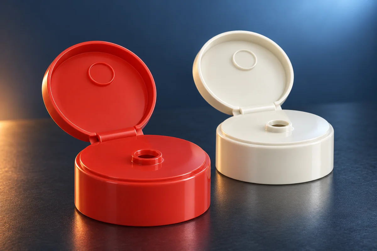
Cosmetic flip top closure

Sauce dispensing flip top closure
What We Need to Evaluate Your Flip Top Cap Project
Send as much of the following information as available. If some data is missing, we can identify the key points during the initial engineering review. If a design remains unproven, define what prototype moulding needs to establish before committing to production tooling.
- Product sample or 2D / 3D drawing
- Cap material
- Neck or bottle matching information
- Required cavity number or target output
- Injection-machine model and main specifications
- Hot runner or cold runner preference, if already decided
- Automatic closing requirement
- Surface finish requirement
- Any existing production problem the new mould should solve
FAQ
Flip Top Cap Mould FAQs
What information is required to quote a flip top cap mould?
A product sample or drawing is the best starting point. Injection-machine information, cavity requirements, material and automation expectations allow us to evaluate the mould more accurately.
Can a flip top cap mould close the cap automatically?
Yes, depending on the cap geometry and project requirements. Automatic or in-mould closing must be evaluated together with hinge design, mould movement and ejection.
Should I choose a hot runner or cold runner flip top cap mould?
The answer depends on cavity count, production volume, cap weight, material, injection-machine capacity and investment requirements. We evaluate both the mould and production conditions before recommending a system.
How many cavities should a flip top cap mould have?
There is no single correct cavity number. It should be matched to target output, cap dimensions, mould size, machine tonnage, shot capacity and automation requirements.
Can you design a mould for my existing injection machine?
Yes. We recommend checking tie-bar spacing, clamping force, mould-height limits, nozzle, locating ring, shot capacity and opening stroke before finalising the design.
What determines the service life of a flip top cap mould?
Steel selection, heat treatment, mould structure, cooling, moving-component design, production conditions and preventive maintenance all influence mould life.
Flip-top mould trial videos
Selected videos from our project archive. Each clip relates to its own tooling or product example. Select Play to load the YouTube player.
Flip-top mould with in-mould closing
Archive video from Mincong Mould’s YouTube channel.
Watch on YouTube ↗Flip-top cap mould trial
Archive video from Mincong Mould’s YouTube channel.
Watch on YouTube ↗PRODUCT SHOWCASE
Explore Related Packaging Moulds
Explore related tooling for your packaging project. Each page explains its own scope and quotation requirements.
ORAL CARE CLOSURES
Toothpaste Flip-Top Cap Moulds
Review tube fit, dispensing, lid engagement and hinge movement before tooling.
Explore product →
24/410 Flip-Top Cap Mould

Oval Flip-Top Cap Mould
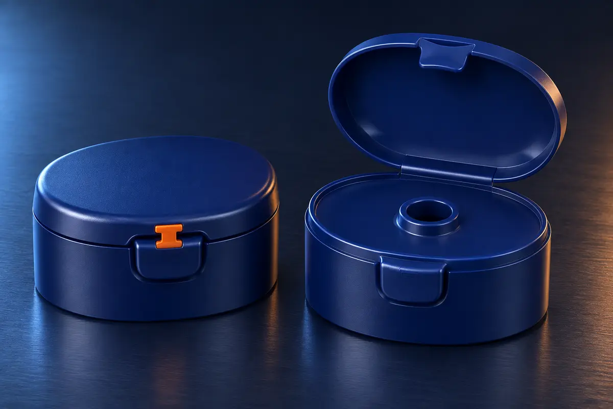
Tamper-Evident Flip-Top Cap Mould
Snap-on closure tooling with a lid-level first-opening indicator.
Explore product →
Wet Wipe Lid Injection Mould
Tooling for resealable PP flip lids on flexible wipe packs.
Explore product →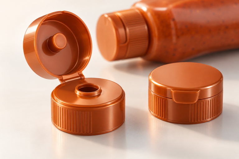
SAUCE DISPENSING CLOSURES
Sauce Flip Top Cap Moulds
Review sauce dispensing, bottle fit, hinge, sealing and the required closing process.
Explore product → Concept illustration
DUAL DISPENSING CLOSURES
Dual-Flap Seasoning Cap Moulds
Define shaker and pour openings, two hinges and the required closing sequence.
Explore product → Concept illustration
SHAMPOO FLIP TOP CAP MOULDS
Shampoo Flip Top Cap Moulds
Review dispensing, hinge, latching, appearance and the required closing process.
Explore product →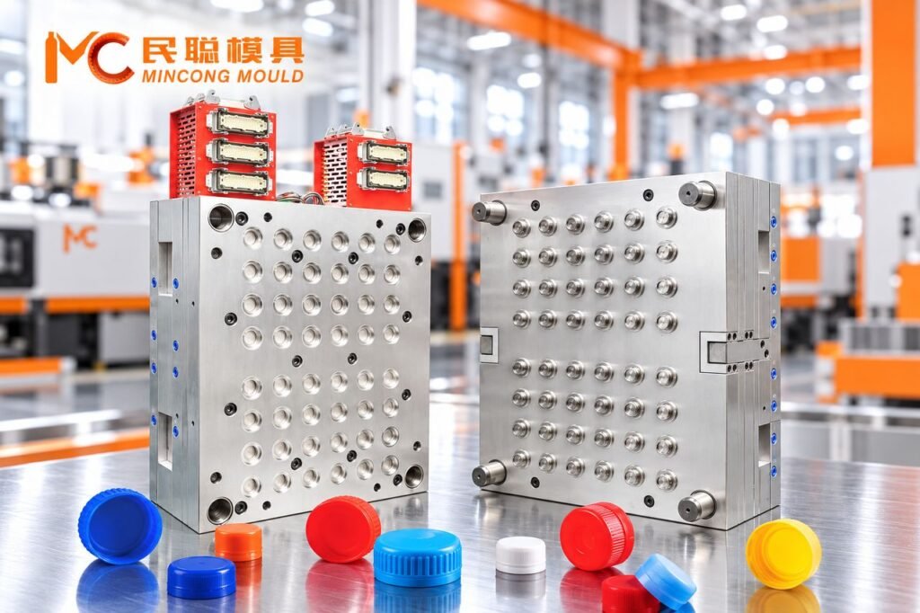
BEVERAGE CLOSURES
Water & Beverage Cap Moulds
Review cap tooling around the bottle neck, closure structure and production requirements.
Explore product →
FUNCTIONAL CLOSURES
Oil & Functional Closure Moulds
Explore tooling for oil caps, dispensing features and defined opening arrangements.
Explore product →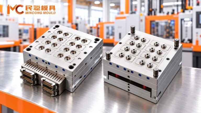
CONTAINER HANDLES
Handle Moulds
Review handle tooling around container fit, load requirements and release.
Explore product →Have a Flip Top Cap Project?
Send us the sample, drawing or injection-machine information first. We can evaluate the mould structure and machine compatibility before you commit to tooling.