A useful injection molding DFM review should improve the design, not simply produce a list of warnings. For a plastic cap, the important question is what to change while preserving the seal, assembly and release requirements.
The practical route is to connect each concern with a design option, its trade-off and a check that can confirm the result. The following approach is a proposed review method for closure tooling; it is not a universal set of dimensions.
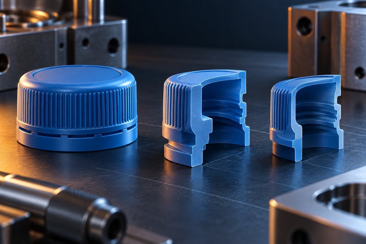
Replace a thick junction with a more balanced section
A thick connection between a cap top, wall and reinforcing feature deserves more than an instruction to increase holding pressure. First ask whether the geometry needs that concentration of material.
One option is to remove unnecessary material from the non-functional side while retaining the required external form. Another is to spread support through a more suitable feature arrangement instead of adding a large solid mass. A gradual transition may be preferable to an abrupt change, provided the revised region can still fill and meet its mechanical duty.
Protolabs' wall-thickness guidance connects uneven sections with shrinkage and appearance problems, and discusses geometry changes such as coring and appropriate reinforcement. The application-specific step is deciding which material can actually be removed from this cap.
For a closure, protect the sealing land and required stiffness while making that decision. The existing cap rib design guide develops reinforcement in more detail.
The trade-off is important: an aggressive reduction can leave a region difficult to fill or too flexible. Review the revised part as a component, not just as a more uniform colour plot in a DFM report.
Solve a draft conflict without losing the required fit
A low-draft wall may be needed to satisfy a mating feature, but that does not make release risk disappear. Begin by identifying where the functional fit actually occurs and how much of the surrounding surface must remain constrained.
Possible responses include adding draft outside the necessary contact region, revising an appearance feature or choosing a different tooling release arrangement. Each needs to be checked against the actual geometry and material. A feature that must move past tooling cannot be evaluated from its static assembled shape alone.
Protolabs' draft guidance explains that suitable draft depends on material, geometry, depth, finish and ejection. It also notes that draft can affect fit. Accordingly, a blanket instruction to add the same angle everywhere is a poor substitute for a feature-level solution.
If the proposal changes a cap-to-neck interface, return to the bottle-neck fit and sealing review. A release improvement that compromises the required interface is not an acceptable resolution.
Move unavoidable marks away from the wrong surfaces
Every design review should consider where feeding and removal leave their effects. A gate or ejector location may be technically possible yet conflict with an appearance panel, assembly contact or sealing feature.
The solution is to compare alternative locations with the relevant surfaces marked. Ask what changes in filling, release and tool complexity when a location moves. Do not approve a location solely because a mark will be less visible.
Ejector design illustrates the trade-off. Protolabs describes how part geometry, material, draft and available contact area affect ejector arrangements. On a cap, the review should therefore include how the removal force is supported, as well as where a witness mark may appear.
Where an alternative is proposed, ask for a revised layout showing the affected regions. This is more useful than a statement that the tooling team will hide all marks later.
Change the release route when geometry adjustment is insufficient
Some conflicts cannot be solved by polishing or a small draft change. A retaining feature, thread or other undercut may require a different release concept, subject to the material and component design.
Compare the available routes against the feature's job. A proposal to simplify release must preserve the required retention or assembly behaviour. Conversely, selecting a more complex mechanism should come with a reason the product needs it.
Use the cap undercut and release guide for that mechanism discussion. The DFM decision is whether to retain the product feature and accommodate it, revise the feature, or accept a documented limitation.
Turn the preferred option into a release decision
A proposed design review can use the following compact comparison:
| Finding | Possible response | Requirement to protect |
|---|---|---|
| Concentrated material at a junction | Remove non-essential mass or revise support | Strength, filling and sealing geometry |
| Draft conflicts with a contact feature | Limit the constrained region or revise release | Required fit and removal behaviour |
| Gate or ejector overlaps a critical surface | Compare alternative locations and layouts | Appearance, interface and filling |
| Undercut prevents the proposed movement | Revise the feature or tooling mechanism | Retention, assembly and reliable release |
These are options to evaluate, not findings from a Mincong customer project.
For the selected option, attach the revised geometry and name what still requires calculation, simulation or trial evidence. A simulated improvement is a prediction until checked on the relevant tool and process. Keep approval of the component separate from approval of the detailed mould design.
Give the supplier a problem that can be engineered
Instead of asking for a general DFM pass, identify the requirement that cannot be lost: a seal, an assembly relationship, an appearance surface or a release constraint. Then ask the supplier to compare solutions around it.
For a flip-top cap mould project, send the drawing, resin and unresolved design questions through the project enquiry form. The desired output is an agreed design route with clear consequences, not merely a completed checklist.