Ejector pin marks become a tooling problem when the contact leaves unacceptable deformation, whitening, a raised or recessed witness, or damage to a required surface. The correction should reduce the load and improve how the part is supported, rather than simply make the mark harder to see.
This article concerns packaging components with ejector pins. A cap mould may instead use a stripper ring, plate, unscrewing arrangement or another release system. Confirm the actual mechanism before applying a pin-based remedy.
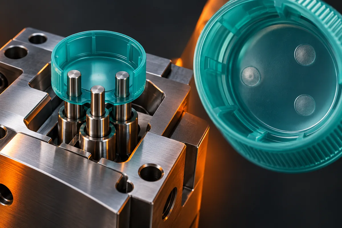
Separate an agreed contact witness from release damage
Locate the witness on the approved part drawing and identify whether it lies on a cosmetic, sealing, assembly or load-bearing area. Compare it with the accepted reference. A permitted contact mark and a newly damaged region should not share one acceptance label.
Check the first accessible stage at which the mark appears. A defect formed during ejection needs a different response from a later impact or handling scuff. The drag-mark guide explains that stage comparison in more detail.
Agree what needs improvement: depth, protrusion, whitening, local distortion, visibility or function. Without that distinction, a supplier can improve the photograph while leaving the actual assembly concern unresolved.
Reduce the resistance before increasing the pushing force
Review the surfaces and features the component must move past. Draft, texture, local interference, retaining geometry and the release sequence can all matter. A stronger actuator or faster movement may force the part out while increasing the damage.
Where the evidence points to resistance, compare permitted geometry or surface corrections with the product's function. Adding release clearance outside a necessary contact region may be feasible; changing a snap or sealing feature without checking the mating component is not an equivalent solution.
If the part requires a different release route, return to the undercut and release review. Pin enlargement cannot remove a fundamental interference that the tool still asks the polymer to pass.
These are design-review options. The actual change needs a defined location and responsibility for the revised fit and release checks.
Spread the load onto suitable support areas
Protolabs describes the relationship between material, part geometry, contact area and ejector arrangement. A soft or locally flexible part may need a different support approach from a rigid component with a broad flat region.
The tooling designer can compare a larger permitted contact area, additional appropriate support or a revised distribution. Evaluate the force path through the part, not only the number of pins. Several contacts concentrated around one unsupported feature may still deform it.
Changing the contact pad can also change local wall thickness. Protolabs notes that a raised pad can increase sink risk while excessive recessing can leave insufficient material. Keep both sides of the component visible in the review, including any appearance face opposite the pin.
For a bottle handle, for example, the support proposal should protect the container attachment and carrying geometry. It should not weaken a loaded section merely to move a witness into a less visible place.
Check whether the part can carry the release load at that stage
A local impression can reflect a part that is insufficiently firm when pushed. Compare the release condition with the material, wall sections, cooling arrangement and intended cycle before changing steel.
A controlled adjustment to cooling or the ejection sequence may be appropriate for the responsible process team to evaluate. Extra time should have a defined purpose; it should not become an indefinite substitute for unresolved cooling or support differences.
Conversely, do not assume that the longest possible cooling phase will always minimise release resistance. Material behaviour and contraction around the tooling also deserve consideration. Choose the comparison from the actual component and its operating window.
Retain dimensional and assembly checks after the selected adjustment. A smaller pin witness does not show that shrinkage, fit or the rest of the part has remained acceptable.
Correct the ejector condition and movement where necessary
Have qualified personnel inspect the relevant pin ends, guidance, alignment and movement against the installed design. Consider whether the contact positions are moving as intended and whether one local point is carrying an abnormal load. Use the tool's maintenance procedures for service work.
A worn or damaged component may need replacement or a controlled repair. A design change to the end shape or contact height needs a drawing review; a cosmetic instruction to make every pin flush can conflict with the intended part contour.
Where the witness is functionally acceptable but poorly located, compare relocation with the filling and release requirements before approving it. The DFM solutions guide addresses that earlier design decision.
Approve the repaired part under the relevant load and fit conditions
Compare the original and corrected samples under the agreed viewing and measurement conditions. Cover the affected cavity positions and repeat the functional checks associated with the changed region. For a carrying part, that can include the specified attachment and load assessment on the matching container.
For a plastic handle mould enquiry, provide the component and container drawings, resin, mark location and acceptance requirement through the project inquiry form. That gives the review a clear choice between reducing resistance, improving support, restoring mechanism condition and changing the contact layout.
Technical references
General technical references; project settings follow the specified material and installed equipment documentation.