A flash defect in injection molding is excess plastic extending beyond an intended part boundary at a mould interface. On a cap, the first decision is where that material is located and what the edge must do. A visible seam, an offset between surfaces and a thin fin of surplus plastic are different observations.
Use the cap defect trial-record guide for sample identity and setup records. Here the focus is the edge itself: how to describe it, decide its importance and accept a correction without concealing another problem.
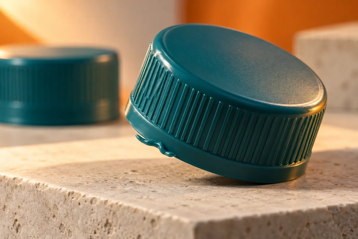
Separate flash from the normal split and from mismatch
The parting line follows the interface between moulding surfaces. Its position is a design consideration. Protolabs’ parting-line guidance explains that this location can affect appearance, tool release and subsequent finishing.
When inspecting a suspect cap, preserve a profile view as well as a whole-part view. Is there a thin extension of material beyond the intended contour? Are adjacent moulded surfaces offset? Is the visible line simply the expected trace of an approved interface? More than one condition can be present, so record them separately.
Avoid accepting or rejecting a cap solely because someone calls the mark a “parting line.” The useful reference is the approved part geometry and the agreed edge requirement. If the intended boundary is unclear, resolve it with the drawing and reference sample before discussing a repair.
Rank the edge by its job on the closure
For a buyer, an edge map is more useful than a general promise of “no burrs.” Ask the team to mark the relevant surfaces on the part and state how each will be assessed. The table below is a proposed project review, not a universal pass/fail classification.
| Cap location to review | Question to agree before acceptance |
|---|---|
| Sealing or mating region | What clearance, contact and package-function checks apply? |
| Lid latch or engagement feature | How will seating, opening and repeated operation be checked? |
| Dispensing opening or product-contact region | Does the specified opening remain clear, with no unacceptable attached or loose material? |
| User-handled edge | What edge condition is allowed for the intended handling? |
| Display surface | Which visual reference and viewing conditions define acceptance? |
Do not apply every row automatically to every cap. Select the requirements that belong to the actual closure. For a flip-top design, identify whether the concern is on the body, lid or a feature involved in closing. Keep the affected location visible after assembly if the chosen inspection method requires it.
Locate the tooling interface before choosing an action
Protolabs’ flash guidance identifies several places where excess material may form, including parting interfaces, vents and moving or insert interfaces. A photograph should therefore help the tooling team locate the corresponding contact—not merely show that an edge looks rough.
We recommend recording the angular position or other usable part reference, the cavity identity where available and whether the feature repeats. Relate that position to the approved tool documentation. If the concern follows an ejector or insert boundary, name that interface rather than grouping it with every mark around the skirt.
If inspection is proposed, define its scope first. Is the task to check cleanliness, damage, fit or another specified condition? Keep routine inspection separate from permission to polish an edge, deepen a vent or rework a shutoff. For the service record and restart process, use the cap mould maintenance guide.
Evaluate clamp and process evidence without guessing from tonnage
Autodesk lists injection and packing conditions, together with insufficient clamp force, among potential contributors to flash. INEOS’s historical PP guide also identifies mould-face contamination as an inspection area. These are possible investigation routes, not a diagnosis of the cap in front of you.
Ask what evidence supports the proposed next action. If clamp capability is questioned, review the actual tool and machine assessment. The number printed on the machine is not a complete explanation of the observed edge. Our machine-compatibility guide covers the wider installation and clamping review.
If the process team proposes an adjustment, ask for a baseline, the changed condition and identified comparison samples. Check the entire result rather than only the disappearance of the fin. A change that reduces excess material but leaves another feature incomplete has not established an acceptable production condition; the short-shot guide covers that separate observation.
The team should select settings under the installed machine and mould instructions. This article does not instruct an operator to increase clamp force, reduce pressure or alter a vent by an unspecified amount.
State whether the inspected sample has been trimmed
For tooling acceptance, distinguish the cap as moulded from the cap after any finishing operation. A carefully trimmed sample demonstrates the result of that finishing step. It does not establish that the mould produces the same edge without it.
If the quotation assumes no separate trimming operation, make that boundary explicit in the sample review. If a finishing operation is deliberately included, identify it in the production scope and agree its effect on output, handling and inspection. Do not allow an unrecorded bench operation to become a hidden production requirement.
Retain an untrimmed reference with the finished sample when finishing is part of the comparison. Identify which version was used for each functional check. This makes the result traceable without prescribing a particular trimming method.
Close the issue with an edge-specific acceptance record
Ask the buyer and supplier to agree the marked location, sample condition, inspection method and decision. Where a measured limit is required, define the feature and method instead of borrowing a generic flash thickness from another product. Set the sampling coverage and repeatability requirement for the actual order.
For a flip-top cap mould, include the affected edge, intended closing operation and applicable engagement or dispensing checks in the enquiry. Send the available drawing, reference images and production requirement through the mould review form. A defined edge requirement gives both teams a practical basis for judging the proposed tool and trial result.
Questions buyers ask
Does every visible parting line mean the mould has flash?
No. Identify whether material extends beyond the intended boundary, whether there is mismatch or whether the expected interface trace is being observed. Acceptance depends on the approved geometry and requirement.
Will a larger machine always solve flash?
No. Clamp capability is one investigation area. The observed location, tooling condition and process evidence still need review before choosing a remedy.
Is removing the fin enough to approve the cap?
Only if the agreed production scope and acceptance checks are satisfied. Record any finishing operation and verify the functions relevant to the affected edge; appearance alone does not establish those results.