A useful injection molding analysis should resolve a design decision, not merely produce a colourful cap image. Define the concern, compare feasible alternatives on the same basis and decide what the trial must verify. A calculation can help reduce uncertainty before steel changes; it does not independently prove mouldability, strength or an accepted production cycle.
Ask one engineering question first
For a cap with an opening, for example, the question might be whether a proposed gate location moves the meeting of flow fronts away from a loaded region. Another study may compare a local wall transition to reduce hesitation. These are different objectives and need different acceptance measures.
State what would make one option preferable. That might include the location of a predicted meeting region, a feasible pressure requirement or a more balanced fill sequence. Avoid accepting “the colours look more uniform” as the decision criterion. Name the functional surfaces and any design features that cannot change.
Make the compared options physically buildable
Use a controlled drawing revision and the intended resin data. Define the feed arrangement, relevant process assumptions and thermal boundary conditions appropriate to the study. If the model omits a runner, cooling detail or machine limitation that matters to the question, explain the omission before using the result.
Do not propose a gate location that cannot be manufactured, serviced or released within the actual tool. Have the tooling review check access, parting, ejection and any hot-runner constraints before spending effort comparing that option. A mathematically attractive alternative may not be a practical mould design.
Read the sequence, not only the final image
For a flow-front question, examine how filling progresses. A final filled image can conceal a delayed region or the point at which paths divide and reunite. Autodesk notes that predicted weld-line representation also depends on the analysis setup and model resolution; absence of a displayed line is not proof that none will appear on a moulded part.
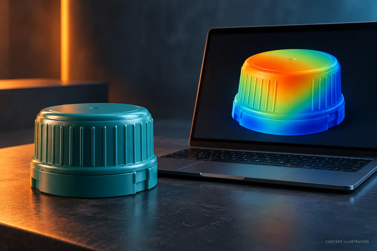
Compare the same outputs for each alternative. Keep the explanation connected to the original question: which change altered the flow path, what new risk it introduced and which limitations remain. The image accompanying this article is an editorial concept, not a Mincong simulation result.
Test whether the conclusion survives uncertain inputs
A result that changes substantially with a plausible resin or process assumption is a development risk, not a robust selection. Ask the analyst to identify sensitive inputs and, where justified, compare a reasonable range based on supplier information and the intended equipment.
This does not mean trying arbitrary settings until the model produces a favourable picture. Preserve the baseline and explain each comparison. If the material model or boundary conditions are not adequate for the proposed decision, obtain better inputs or narrow the conclusion instead of presenting false precision.
Convert the selected option into trial checks
Link the chosen model revision to the released tool drawing. Identify the observations needed during sampling, such as a controlled filling sequence, cavity-identified parts and inspection of the relevant region. Establish the agreed functional tests separately; a predicted line location does not quantify the strength of the actual closure.
If trial observations disagree, first compare the built geometry, material and operating conditions with the study. Correct a model mismatch before deciding that the underlying design needs another steel change. Equally, do not dismiss a repeatable part problem because the simulation looked acceptable.
Define analysis scope in the RFQ
Specify the question, deliverables, model revision, material basis and review responsibility. State whether the quoted work includes only filling, additional thermal or deformation assessment, or trial correlation. Software choice and deliverables should be explicit; this article does not claim that a particular study or software service is automatically included in a Mincong mould quotation.
Send the cap files, resin specification and the decision that needs support. A focused study can then be discussed alongside the tooling proposal, with a defined route from calculated comparison to physical acceptance.
Continue the project review
Water & Beverage Cap Mould · Injection Molding DFM: Practical Design Fixes Before Tooling · Cavity Balance in Injection Molding: Correct Fill Differences Before Raising Pressure
Send drawings and project requirements →
Technical references and scope
General application and engineering references checked on 31 October 2026. Supplier examples do not establish Mincong project performance or supply relationships. The review and selection steps above are engineering proposals for the defined project.