Injection mold cooling design needs a defined supply condition as well as a channel layout. For a cap mould buyer, the practical question is whether the proposed circuits can operate with the utilities at the receiving factory—and whether the accepted trial connection can be reproduced there.
Ask for the circuit plan and the plant-side assumptions before design approval. A drawing showing blue passages does not establish the flow through each branch. Our cooling-time guide covers estimates and cycle evidence; this article addresses the cooling-system handover.
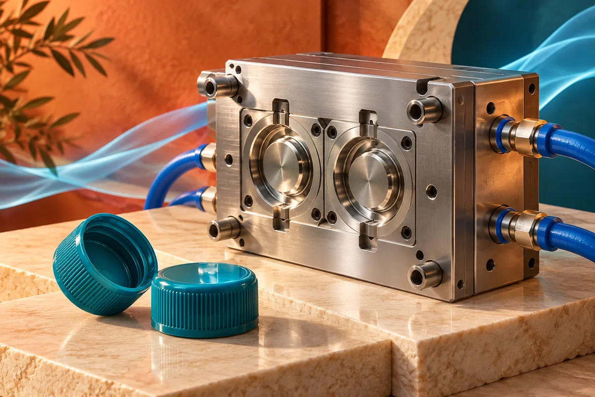
Give the designer the supply conditions at the intended machine
Autodesk's cooling-circuit guidance says available coolant flow should be known before mould design. It also explains that total flow divides between circuits according to their pressure losses. The buyer's utility information therefore belongs in the design review, rather than arriving after the mould is finished.
Identify the coolant, temperature-control equipment, connection arrangement and available supply and return conditions. Ask the plant team which values describe the intended connection while operating, rather than a pump's maximum rating or an equipment catalogue value. Mark unmeasured assumptions as open items.
For a trial at the toolmaker's factory, agree how its supply will be compared with the receiving plant. If they differ, record the difference and the proposed follow-up. A successful trial remains useful evidence, but it does not establish identical conditions at another installation.
Make every connection traceable to a circuit
Request a connection schedule that ties each inlet and outlet identifier to the controlled circuit drawing. It should show which part of the mould the circuit serves and how any external links are connected. Identify separate temperature-control groups where the design uses them.
A useful handover lets the receiving technician match a port label on the mould to the drawing and the trial record. Ask whether the delivery includes the external hoses, couplings and distribution components used during acceptance. If some are supplied by the buyer, specify that boundary before comparing quotations.
For a multi-cavity cap mould, also ask how the thermal plan relates to the cavity layout. This is a request for the designer's explanation, not an instruction to assign one circuit to every cavity. The proposed grouping needs to fit the actual geometry and supply conditions.
Review series and parallel arrangements at the branch level
Autodesk's series and parallel circuit explanation describes the trade-off: parallel branches can carry different flows because their resistance differs, while a long series path may demand more pressure than the available pump can provide. Adding branches does not by itself establish adequate cooling everywhere.
Ask which flow condition the design assumes for each relevant branch and how it will be checked. A reading for the combined return should not be presented as a measurement of every branch. Keep the measurement scope visible beside the result.
Consider a hypothetical handover in which the trial uses separate controlled connections, but the receiving plant proposes joining them onto one distribution line. Treat that as a changed setup to review. The illustration is a purchasing example, not a report of a Mincong project or proof that either arrangement will fail.
Identify restricted or difficult-to-reach cooling areas
Autodesk's baffle and bubbler documentation explains that these components direct coolant toward areas ordinary channels cannot effectively reach. Their restricted flow areas can also create significant pressure losses. They are design options to assess, rather than automatic upgrades.
Ask whether the proposed tool uses such features, where they appear on the circuit schedule and how their condition can be checked within the supplied maintenance instructions. Do not infer an internal arrangement from the outside hose count.
Smartflow's low-flow indicator information distinguishes detecting the presence of movement in restricted passages. For acceptance, agree whether an installed device indicates movement or measures a quantity needed by the project. Record the instrument and its applicable range instead of treating a moving indicator as a complete thermal assessment.
Put measurement locations into the acceptance record
Before the trial, agree a short record linking the connection arrangement to measured conditions. The following is a proposed project format, not a universal inspection standard:
| Handover item | Evidence to retain |
|---|---|
| Circuit identity | Port labels, circuit drawing revision and external connection schedule |
| Supply boundary | Coolant definition, relevant equipment and agreed plant-side conditions |
| Flow evidence | Identified circuit or branch, method, units and measurement location |
| Thermal evidence | Relevant supply and return measurements, with locations and collection time |
| Connection condition | Agreed leak-check record and the external components included in delivery |
| Accepted result | Identified cap samples, trial conditions, exceptions and approval record |
Keep equipment setpoints separate from measurements at identified locations. Define the condition under which readings will be collected, including the agreed point in the trial. The aim is a reproducible comparison, not the largest collection of isolated numbers.
The tooling and plant teams should agree any checking procedure under the installed equipment and component instructions. This handover format supplies no test pressure, operating setting or permission to modify a circuit.
When water appears on exposed cold steel, use the mould condensation and dew-point guide to separate a leak from ambient condensation before changing the cooling setup.
Preserve the accepted setup through shipment and installation
Deliver the accepted connection schedule with the mould, together with the relevant operating and service documentation. Identify any difference between the trial arrangement and the shipped scope. At installation, compare the actual connections with that record before attributing a changed cap result to the steel or the resin.
Use the mould maintenance checklist when investigating a change in an existing circuit. Use the machine-compatibility guide for the wider installation boundary. Neither replaces the cooling circuit's own accepted record.
For a new water or beverage cap mould, send the closure definition and available plant utility information through our project review form. Agreeing these inputs early gives the cooling proposal a practical basis for design, trial and handover.