If a moulded tube has a thin wall on one side and a thicker wall opposite it, restore the core-to-cavity relationship before accepting a heavier shot as the fix. Separate an offset present in the closed tool from core movement under filling pressure. Those conditions can produce similar parts but require different corrective work.
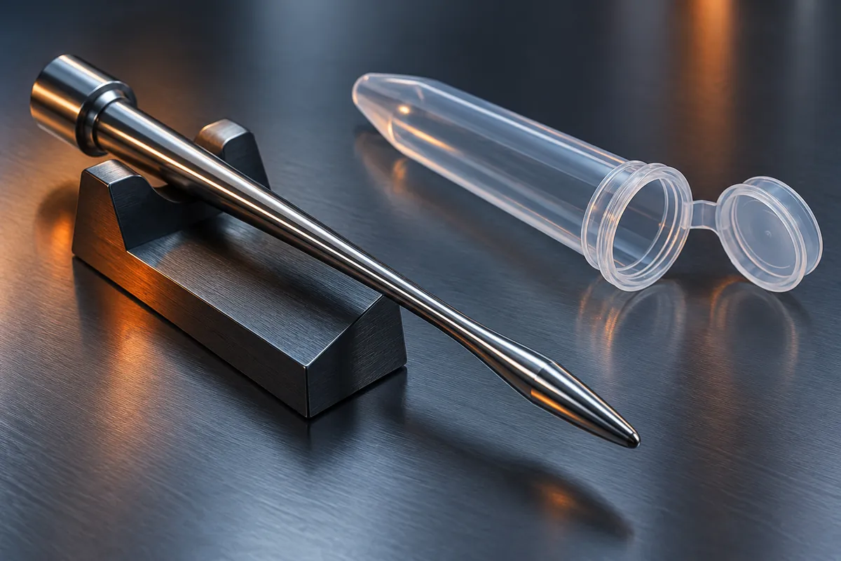
Establish which relationship has moved
Inspect the approved internal and external geometry at agreed positions along the part. Compare circumferential wall measurements from identified cavities and consistent sample conditions. A single outside diameter or an average part weight can miss the local thin region.
A repeatable offset suggests a locating, machining or assembly question worth checking. A pattern that changes with filling conditions may indicate a load-sensitive problem. Neither observation is a diagnosis on its own: dimensional inspection of the tool and a controlled process comparison are needed before steel is altered.
Restore fixed alignment and support first
Check the locating and seating surfaces, core condition, relevant guide or locking components and the mould assembly against its drawings. Remove an identified assembly or wear fault through the qualified tooling procedure. Replacing the core alone is unlikely to solve a damaged locating seat that positions the replacement incorrectly.
Include the support available from the mould plates and installed machine. Autodesk's core-shift guidance distinguishes alignment error, plate deflection and pressure-driven core bending. Its flow-coupled core-shift analysis addresses the latter; a predicted result does not clear the real tool of the other causes.
Reduce the unequal load on the slender core
Once the mechanical reference is sound, compare how melt reaches opposite sides of the core. Gate position, flow path and local wall geometry can produce unequal pressure during filling. A proposed change should explain which imbalance it is expected to reduce.
Evaluate feasible filling-profile or thermal changes within the actual resin and equipment limits. If lower loading improves wall balance but causes incomplete filling, that is a trade-off to resolve, not an acceptable production setting. Review support, gate or geometry alternatives rather than simply choosing one defect over another.
Keep thermal and release effects in the investigation
Check that the intended cooling arrangement is working and that the core is not being evaluated under an abnormal temperature condition. A restart, a disturbed circuit and a thermally settled run should not be compared as though they are identical.
Also establish whether distortion appears after mould opening or handling. Release damage can alter the final shape even when the forming geometry was acceptable. Compare the wall and shape at relevant inspection stages before assigning every eccentric-looking sample to core bending.
Choose the intervention from a controlled comparison
| Supported finding | Intervention to evaluate |
|---|---|
| The core is incorrectly located before injection | Restore the drawing-defined seat and assembly relationship before tuning pressure. |
| Mechanical location is sound but wall imbalance changes with filling load | Compare flow symmetry and core support together; retain complete filling and functional acceptance as constraints. |
| The formed part changes mainly during release or handling | Correct the release and handling load before assuming a new core is required. |
These are decision routes, not a diagnosis from one sample. If a proposed process adjustment only moves the defect to a different region, reopen the structural or flow review rather than accepting the new pattern.
Prove the correction where the failure occurred
After the selected repair or design change, repeat the wall inspection at the same positions and include the component's required functional evaluation. For a laboratory tube or syringe component, the customer-defined fit, containment or other application checks remain separate from a simulation image.
Repeat the comparison across the intended cavity set and operating conditions before increasing output. A stable total shot weight cannot prove that every slender core remains correctly positioned. Send the component drawing, wall map, cavity pattern and relevant process changes when requesting a tooling review; those inputs support a targeted correction rather than an assumed core replacement.
Related engineering resources
- Medical Packaging Mould
- Syringe Barrel Moulds for Defined Bore and Interface Requirements
- Pipette Tip Moulds for Defined Fit, Outlet and Release Requirements
- Injection Molding Analysis for Caps: Turn Simulation into a Design Decision
Technical references and scope
Supplier examples describe their own products. They do not establish Mincong certification, supplier affiliation or a validated project result. Proposed checks must be agreed for the specific component, resin and production equipment.