Jetting in injection molding is associated with a stream of melt entering the cavity without first developing a suitable flow front against the mould surface. It can leave a winding surface pattern, but not every line near a cap gate is jetting.
The principal corrective routes are to control the early filling stage and, where needed, improve how melt enters the cavity. A cap project should evaluate those routes against the real gate, material and filling sequence, rather than apply a universal reduction in injection speed.
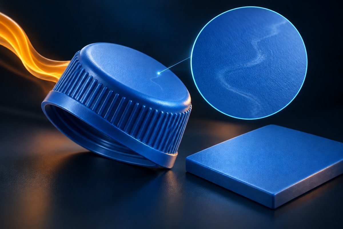
Target the start of filling instead of slowing the whole shot
Autodesk's jetting guidance recommends an initial slower passage through the gate, followed by a higher filling speed after a dispersed flow develops. The distinction between those stages is the useful part of the remedy.
For a suspected jetting problem, ask the process team whether the machine's profile can separate the gate-entry phase from the later fill. Define a controlled trial around that question. Do not copy the transition position or speed from another mould.
An overall slow fill may create a different problem if the component can no longer fill adequately. Retain checks for complete features, appearance and relevant function while evaluating the revised profile.
A useful comparison should show the baseline, the proposed profile and which part of filling changed. It should also explain why the change corresponds to the actual flow stage. A machine setting screenshot alone cannot establish that connection.
Confirm the symptom before repeating the same remedy
A white halo, a raised gate residue and a winding surface trace should not automatically receive the same action. Use the observed pattern to select the next engineering question, then assess whether the trial result supports it.
The gate-blush guide addresses whitening near the gate. The gate-vestige guide concerns residual geometry. Neither is a substitute for a filling investigation.
Where filling evidence is needed, the qualified trial team can select an appropriate observation method within its approved machine procedures. Keep the cap orientation and gate position identifiable. No investigation requires bypassing guarding or collecting parts inside moving equipment.
This short diagnosis stage prevents a common form of wasted work: repeatedly changing a jetting-related parameter when the visible concern belongs to another mechanism.
Bring actual material and system conditions back to the design basis
If the expected response to a profile change is absent, confirm the resin grade and actual processing conditions against the intended basis. Temperature changes should remain within the applicable material and equipment guidance; raising a setpoint until a mark disappears is not a controlled solution.
On a hot-runner tool, ask whether the installed components and operating condition match the approved configuration. Identify a suspected restriction or component problem for the system supplier rather than compensating indefinitely with machine settings.
For a YUDO-equipped project, use the relevant application and service documents. If a Husky system is being considered, confirm its suitability for the proposed Mincong project before treating it as an available solution. Neither name explains the gate-entry behaviour by itself.
Keep servicing, configuration changes and mould redesign as separate actions. This makes it possible to tell whether the result came from restoring the intended system or introducing a new design.
Redirect the gate entry when the geometry promotes a free jet
If process adjustment cannot produce acceptable filling, examine the gate's position and entry direction. Autodesk and Mastip describe directing incoming melt toward a cavity surface as a possible remedy.
For a cap, compare that idea with the actual space, sealing features and acceptable gate location. A relocation is only useful if it remains compatible with the component and tooling requirements.
A revised entry or a more gradual flow-area transition may be considered where the runner and tool design permit it. Gate concepts used in other tooling are not automatically suitable for a high-cavity hot-runner cap mould.
Do not authorise opening the gate without a defined revised design. The change may affect the accepted residue, filling requirements or local tool arrangement. Our sprue, runner and gate guide explains those different elements.
Escalate from a reversible adjustment to permanent work
| Route | Purpose | Decision before moving on |
|---|---|---|
| Trial a staged filling profile | Evaluate the early gate-entry condition | Is the trace improved without a new filling defect? |
| Restore the intended material and system condition | Remove an operating deviation from the comparison | Is the installed setup consistent and appropriate? |
| Compare entry direction and gate design | Address a geometry-related flow mechanism | Is the revised concept compatible with the cap? |
| Implement an approved tooling change | Produce the selected design | What appearance, dimensional and functional checks must repeat? |
This is a proposed escalation path, not proof that all four steps are needed.
Approve the result using identified samples and the original acceptance requirements. A less visible line does not establish that every relevant component property has remained acceptable. Preserve any required package-function checks and record unresolved effects before releasing the change.
For a water and beverage cap mould, send the cap drawing, material and filling concern. The engineering task is to choose an effective intervention for the actual flow path, then demonstrate that it solves the problem without compromising the closure.