To reduce plastic cap warpage, correct the source of uneven deformation rather than changing the cavity to match one unstable sample. Cooling imbalance, inconsistent packing, release forces and the part's own geometry can call for different solutions.
A practical starting order is to restore the intended equipment and cooling conditions, establish repeatable moulding, then consider tool or part changes. This order is an engineering recommendation intended to avoid unnecessary permanent work; the observed cause can justify a different sequence.
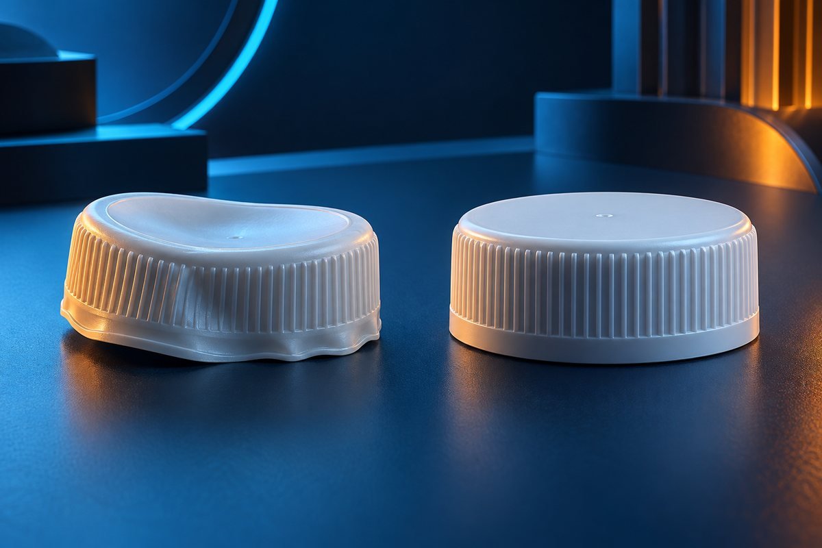
Restore cooling performance before redesigning the circuit
When distortion is associated with a repeatable region or particular cavities, compare their cooling conditions with the rest of the tool. Check actual flow through the relevant circuits, the connection arrangement and whether a blockage or restriction has reduced the intended heat removal.
The first corrective action may be restoring a circuit, not lowering the chiller setting. Confirm that supply and return connections match the approved circuit information, then compare the resulting part shape after the process has stabilised.
Autodesk identifies uneven cooling as a warpage cause, while INEOS' PP guidance discusses mould-temperature control and sufficient cooling before removal. Neither establishes one suitable coolant setting for every cap.
If restoration does not resolve the imbalance, the mould designer can evaluate circuit changes or local cooling provision against the actual tool. More cooling everywhere is not the same as balanced cooling. Our cap cooling circuit guide explains the installation and handover information needed for that discussion.
Make filling and packing repeatable before increasing pressure
A cap shape that varies significantly from shot to shot needs an assessment of process stability. First establish that the intended resin and colour system are being used and that filling, transfer and packing are behaving consistently.
Where evidence points to insufficient or uneven packing, the process team can evaluate the relevant packing conditions within the material and equipment limits. The goal is a controlled comparison, not a series of simultaneous increases.
This route has a trade-off. A shape change that looks favourable may arrive with flash, a changed interface dimension or more difficult release. Include those effects in the comparison. Do not retain a setting solely because the top panel looks flatter.
Material or machine variation can make a permanent correction misleading. Autodesk's warpage guidance includes material, processing and machine inconsistency among the possible contributors. Keep a repeatable process as the basis for deciding whether steel work is justified.
Reduce distortion introduced during release
A cap can leave the cavity with insufficient rigidity or be distorted by the way removal force is applied. If the concern appears during release, evaluate the cooling interval and the actual removal route together.
A controlled trial of sufficient cooling before ejection may help determine whether the part is being removed too early. Where contact or force distribution is implicated, inspect the corresponding tooling and review support, draft and ejection movement.
Possible corrective work includes restoring damaged contact surfaces, resolving an unintended interference, or redesigning how removal is supported. The appropriate route depends on the cap and mechanism. Protolabs' ejector guidance explains why geometry, material and available support influence removal arrangements.
Avoid making higher ejection force the default response to resistance. A successful correction must release the part without creating a new shape, surface or functional problem. Keep approved appearance and mating-part checks in the trial.
Change geometry when stable processing cannot solve the imbalance
A heavy local junction, abrupt thickness change or uneven distribution of stiffness can make a cap difficult to stabilise. If the problem remains under a repeatable process, compare design alternatives.
Possible routes include removing unnecessary local mass, smoothing transitions or redistributing support. These changes should preserve the seal, assembly and required mechanical behaviour. Reinforcement is not automatically beneficial if it introduces another thick junction.
Gate location and flow pattern may also deserve review where the evidence supports a filling-related mechanism. Any relocation needs a new assessment of appearance, filling and interfaces.
A geometry compensation may be considered for a persistent, repeatable shape error, but it should be based on an established process and agreed measurement conditions. Do not use it to conceal an unresolved cooling or machine problem. The HDPE shrinkage review covers the material basis separately.
Choose the corrective route from the evidence
| Observed pattern | A useful first action | What must also be checked |
|---|---|---|
| Repeatable distortion in one tool region | Restore and compare the relevant cooling circuit | Flow, local conditions and other cavity results |
| Shape changes between shots | Establish material and process consistency | Filling, packing and equipment behaviour |
| Distortion appears during removal | Evaluate cooling and release support | Surface damage and mating-part function |
| Stable error persists after process checks | Compare part or tool design changes | Filling, seal, stiffness and release trade-offs |
The patterns help prioritise investigation; they do not prove a cause on their own.
Accept the correction on the complete closure
Define the measurement timing, reference condition and whether the cap is assessed freely or assembled. Then compare the baseline and proposed solution under that same basis.
For a water and beverage cap mould, a flatter panel is only one result. Confirm the relevant fit, assembly and sealing requirements as well. Keep an improvement that satisfies the complete acceptance criteria rather than trading one defect for another.
Send the cap drawing and warpage concern for review, together with cavity-identified samples and the current process information. That allows the next proposal to address a specific mechanism instead of guessing at a universal setting.