An injection mold texture should produce the intended surface while allowing the cap to fill, release and function correctly. Selecting a rougher pattern is not, by itself, a solution to an appearance problem.
For closure projects, a useful route is to divide the cap by surface function, choose a finish with the actual resin and release direction in mind, and resolve the difficult regions before final finishing. This keeps the appearance decision connected to the tool design.
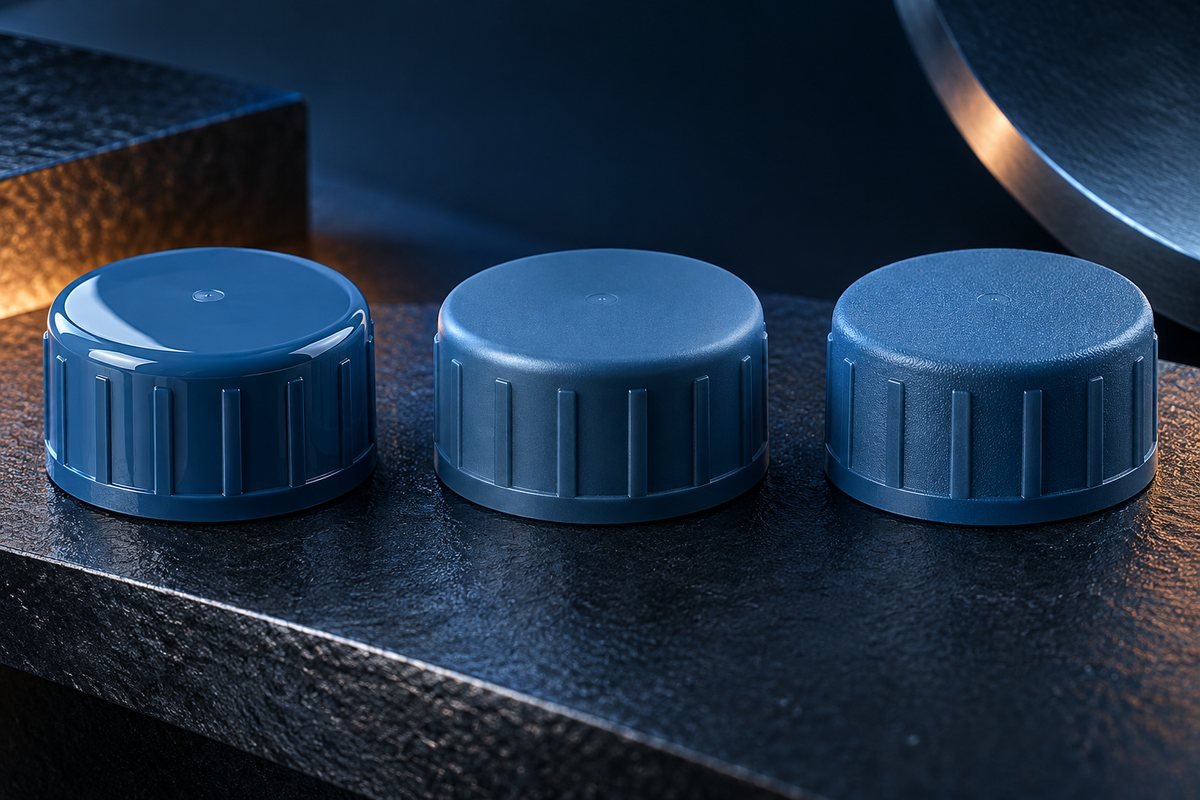
Use different finishes where the surfaces have different jobs
A grip area, visible top, sealing land and assembly feature do not automatically need the same surface treatment. Applying one texture across the whole part can create an avoidable conflict.
Start with a marked model that shows where the desired appearance begins and ends. Keep surfaces governed by sealing or assembly requirements under their own specification. Where a finish meets an edge, parting line or insert boundary, show how that transition should look.
For example, a hypothetical flip-top cap may use an appearance finish on the lid while retaining a separately specified surface on the sealing feature. The point is to locate the requirement, not to recommend that arrangement for every lid.
This creates a practical solution when a full-surface texture is difficult to execute: limit the treatment to the areas that provide the intended value, rather than forcing the same finish onto every functional detail.
Solve texture and release together
Texture can increase the draft needed for clean release. If a deep or constrained wall cannot accommodate the proposed finish, compare the design options before texturing the steel.
Possible responses include a less demanding texture, additional permissible draft, a smaller textured region or a revised tool-release concept. The choice depends on the actual material, feature and appearance requirement.
Protolabs' draft guidance explains that one angle does not suit every part, and its surface-finish guidance identifies the link between texture and release. Consequently, a generic texture-depth-to-draft rule should not replace the tool designer's review of the specific cap.
Changing only the ejection action may leave the geometry conflict unresolved. If a part already shows release-related scuffing, use the cap drag-mark guide to identify the damage stage before authorising local work.
Use the production material to resolve an appearance mismatch
A finish that looks right on one material may not look the same on another. Protolabs identifies resin characteristics, fillers and colour as influences on the visible result.
The practical response is to compare a suitable reference made with the intended material and colour where possible. A photograph of an unrelated black sample is a weak basis for approving a white or translucent production cap.
If an initial sample looks different from the target, compare material, surface treatment and moulding conditions before ordering a different texture. The steel may not be the only variable.
Where the final colour or formulation is still open, treat appearance approval as provisional. Resolve that dependency before declaring the finished tool's cosmetic requirement complete. This is especially useful when a project changes colour late in development.
Correct uneven appearance at the right level
A visible mismatch can lead to several different actions:
| Concern | Candidate solution to evaluate | Constraint |
|---|---|---|
| Intended texture cannot release cleanly | Adjust permitted draft, texture or treated area | Preserve interface and overall form |
| Finish differs from the reference | Align resin, colour and comparison conditions | Avoid changing steel for a material mismatch |
| A local tool repair stands out | Define the preparation and finishing boundary | Keep neighbouring geometry and texture controlled |
| A witness mark interrupts the surface | Review gate or ejector location and its acceptance | Do not compromise filling or removal |
| Repeated appearance variation across cavities | Compare surface condition and moulding consistency | Confirm the cause before reworking every cavity |
This table proposes routes for review. It does not classify defects from photographs alone.
For a local rework, specify the region and the surface that must remain unchanged. An open instruction to polish until the mark disappears can remove an intended texture or alter a nearby feature. If geometry is affected, include the relevant dimensional checks after finishing.
Finish the surface at the right point in development
Where geometry is still changing, consider whether final texturing should wait until the affected design is stable. Protolabs' texture guidance notes that existing surface condition and later changes can affect the work required.
Ask the finishing supplier what preparation is needed, how protected regions will be handled and whether a later repair would leave a visible boundary. Do not assume a decorative finish can be added or reversed without consequences.
The proposed approval sequence is therefore component geometry, feasible finishing and release plan, representative appearance comparison, then final verification on the intended part. Any extra lead time or rework scope should be made clear in the quotation.
Approve the appearance and the function
Agree viewing conditions and a retained reference for appearance comparison. Where a surface has a functional duty, keep the appropriate assembly or sealing checks alongside that comparison. A visually consistent finish does not replace a function test.
For a flip-top cap mould, identify the visible lid, grip features and sealing or assembly surfaces in the enquiry. Send the marked drawing and finish reference so the discussion can compare achievable solutions instead of relying on the words matte or polished alone.