MEDICAL CONSUMABLE TOOLING
Blood Collection Tube Moulds for Defined Tube and Closure Interfaces
Mincong Mould develops custom injection moulds for plastic collection-tube bodies, with the proposal based on your approved tube drawing, resin grade and closure interface. This page is for manufacturers evaluating tooling for a defined component, rather than purchasing finished blood collection tubes. Cavity layout, cooling, release and sample acceptance are reviewed together before a configuration is confirmed.
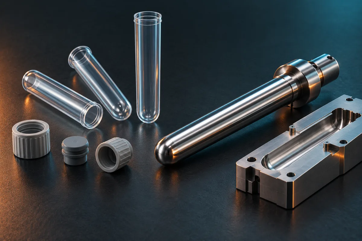
Define the tube body before selecting the tool
A tube can look simple while carrying several different functional surfaces. The mouth must match the intended cap or stopper; the bore, wall and base must follow the component specification; the outside must suit the agreed handling and labelling arrangement. Identify these requirements on the drawing rather than relying on nominal capacity alone.
For an evacuated blood-collection product, the tube body is one part of an assembled system. A tube-body mould does not by itself establish draw volume, vacuum retention, additive compatibility or the performance of the complete device. Provide the mating components and the product manufacturer's acceptance requirements so the tooling scope can address the relevant interfaces.
A tooling proposal built around the critical features
| Tooling area | What the proposal should resolve |
|---|---|
| Mouth and closure interface | Identify the sealing and locating surfaces, permitted witness locations and approved mating components. Keep these features distinct from general appearance areas. |
| Core, bore and wall | Review core support, intended alignment and the wall distribution along the tube and around the base. A nominal outside diameter alone cannot define the internal geometry. |
| Gate and feed arrangement | Select the feed location and runner configuration around the resin, tube geometry, gate residue and maintenance access. Confirm any restricted contact or appearance areas. |
| Cooling and release | Review core-side and cavity-side heat removal, the condition required for release and the way the component is supported during removal. |
| Cavity layout and machine | Check injection capability, mould dimensions, opening travel, ejection and part-removal space against the actual machine and handling arrangement. |
Our engineering review starts with the features that must work together. If the wall distribution is sensitive to core alignment, the proposal needs a support and verification approach. If the closure interface is sensitive to release deformation, the release arrangement and sample conditioning need attention alongside the steel dimensions.
For detailed inspection planning, see our plastic-part tolerance guide. The measurement principles can support the discussion, but the limits and datums must come from the tube specification.
Resin and runner selection follow the actual component
Confirm the exact resin grade and its supplier's processing guidance before comparing tooling configurations. PET is used in commercial blood-collection tube products, but that does not make every PET grade, tube design or production setup interchangeable. Identify colourants and any intended downstream treatment when defining the material basis.
Where a hot runner is proposed, review the nozzle and gate arrangement, temperature control, allowable residue and service access. If YUDO or Husky is specified, the exact configuration and suitability for the material, machine and Mincong project must be confirmed. A brand name alone does not establish that a system will produce an acceptable tube.
The hot-tip versus valve-gate guide explains the general distinction. Selection for a tube must still be made against its own geometry and acceptance requirements; a closure-tool configuration is not automatically transferable.
Cooling and removal must preserve the intended shape
The cooling proposal should account for the long internal surface and the base as well as the outside of the tube. Discuss circuit access and maintenance with the machine-side connections in view. A shorter cycle is useful only if the part retains its required geometry through release, handling and subsequent conditioning.
The ejection method is chosen for the actual tube. The review should identify where removal force is applied, what supports the part and how it is transferred away from the tool. Do not assume that a method used on a short cap will suit a long tube. The proposed sampling plan should detect local wall differences, release deformation and cavity-to-cavity variation before production acceptance.
Agree on the trial and handover scope
Before trial, agree on the material, machine, ancillary equipment, stable sampling conditions and cavity identification. Define the mouth, body, base, appearance and assembly checks that belong to mould acceptance. If an inspection needs a particular gauge, sectioning method or conditioning interval, include it in the agreed plan.
Review tube samples with the approved mating components. The customer's complete-product validation, including any required vacuum, leakage, sterility, analytical or regulatory assessment, remains a separately defined scope. Tool acceptance should clearly state which evidence is being delivered and which later tests are still required.
Request a handover package that matches the purchased scope: approved drawings, relevant cooling and operating information, identification of service parts and the agreed trial and inspection records. Specific documents, spare parts and support responsibilities should be listed in the quotation rather than assumed.
Send the information needed for a useful quotation
Send the tube's 2D/3D drawing or a representative sample, the specified resin grade, the mating cap or stopper, target output and the injection-machine data. Mark the critical dimensions and state the inspection and production-environment requirements. If some inputs are still undecided, identify them so the review can separate an initial tooling concept from a confirmed specification.
Request a collection-tube mould review.
For other component types, explore the medical consumable mould overview or the separate syringe barrel mould page.
Questions before confirming a collection-tube mould
Can a standard cavity count or cycle be quoted immediately?
An initial layout can be discussed, but a confirmed proposal needs the tube geometry, resin, output requirement and machine limits. Cycle acceptance must state the actual moulding and handling conditions; it is not a universal number for every collection tube.
Can the mould include the cap or stopper?
Identify each component in the RFQ. A plastic cap mould can be reviewed as a separate tooling scope. An elastomer stopper, tube assembly and downstream processing must not be assumed to be included in a tube-body mould quotation.
Does the mould quotation certify the finished medical product?
No. State the required tooling documentation and validation support at the quotation stage. Finished-device conformity and approval require the product manufacturer's defined assessment and cannot be inferred from the mould, steel or hot-runner brand.
PRODUCT SHOWCASE
Explore Related Medical Mould Products
Explore related tooling for your packaging project. Each page explains its own scope and quotation requirements.
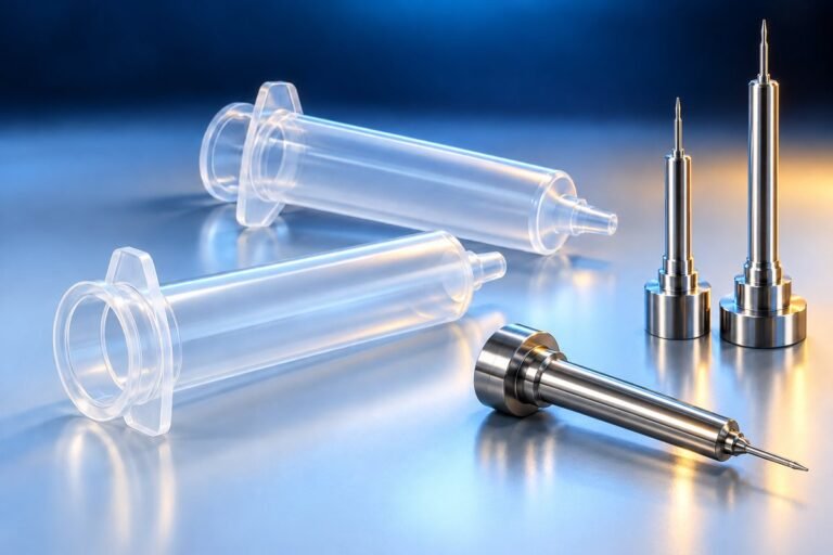 Concept illustration
SYRINGE COMPONENT TOOLING
Syringe Barrel Moulds
Plan the bore, mating interfaces and release around the approved barrel specification.
Explore product →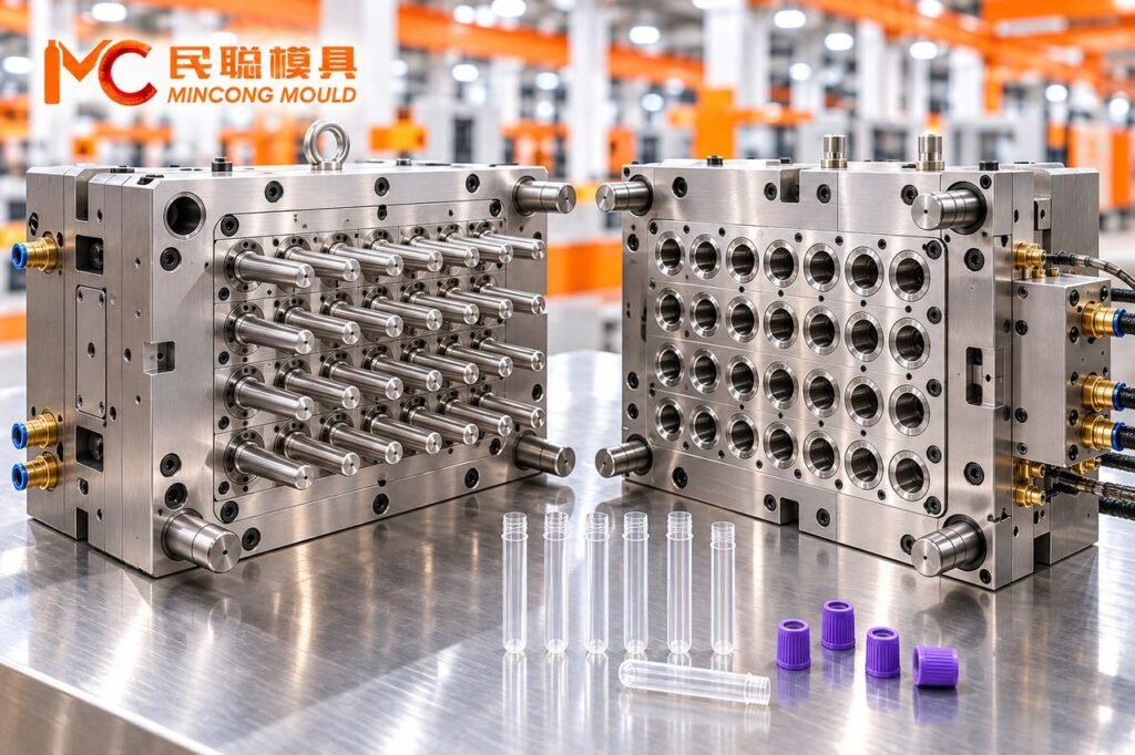
MEDICAL CONSUMABLE TOOLING
Medical Packaging Moulds
Explore the tooling scope for tubes, tips, closures and defined medical components.
Explore product →Images marked as concept illustrations are AI-generated, not project photographs. Review each page for its tooling scope and project-specific requirements.